NEMA Wiring Schematic Manual for Electrical Specialists
Nearly seventy percent of the electrical breakdowns in installations stem from poor wiring methods. Such data underlines the need of adhering to recognized guidelines, highlighting NEMA wiring schematics’ value for electrical experts. Via these schematics, wiring setups that satisfy both performance effectiveness and optimal protection norms are presented.
The aim of this guide is to equip electrical practitioners with deep understanding into NEMA criteria. Emphasizing the significance of accurate electrical installations is essential. By learning these guidelines, practitioners can drastically cut the chance of hazards and ensure they adhere to safety standards endorsed by Installation Parts Supply. Expertise in NEMA l14-30P wiring diagram is crucial whether designing new setups or repairing present ones, as it enhances the capacity to provide secure and dependable electrical answers.
Significant Points
- NEMA wiring diagrams are essential for maintaining electrical security and compliance.
- Adequate wiring methods can minimize electrical malfunctions considerably.
- Grasping NEMA standards boosts the efficiency of electrical installations.
- Installation Parts Supply supports adherence to safety standards in electrical operations.
- NEMA diagrams support a wide range of applications across multiple sectors.
Grasping NEMA Criteria and Why They Matter
NEMA criteria are essential in the electrical domain, guiding protection and operation precisely. Crafted by the National Electrical Manufacturers Association, they establish pivotal criteria for creating, examining, and identifying electrical gear. Such measures guarantee uniformity and reliability across all electrical installations, which is invaluable.
Identify the NEMA Criteria?
NEMA categories span from classes 1 up to 13. Each level defines the criteria suitable for electrical appliances to perform optimally. For example, NEMA 1 provides minimal indoor safeguarding but is missing dust protection. Alternatively, NEMA 4 guarantees devices is watertight, a necessity for withstanding substantial water immersion. Grasping these classifications is key in picking proper appliances.
Why NEMA Standards Matter for Electrical Safety
The function of NEMA standards in ensuring electrical safety is significant. They play a significant part in reducing shock risks, device breakdowns, and fire hazards. Accurate adherence to NEMA classifications allows equipment to function securely under particular surrounding conditions. For open-air application, NEMA 3 classifications deliver protection against the elements, safeguarding the equipment from harsh weather like precipitation and snow. In zones prone to explosions, standards including NEMA 7, 8, and 9 are vital for upholding protection.
Implementations of NEMA Standards in Wiring Schematics
The use of NEMA norms in wiring diagrams is vital for safe, effective electrical setups. These diagrams utilize consistent symbols and structures originating from NEMA ratings, facilitating the interpretation of complex electrical arrangements. This standardizing is beneficial. It encourages lucidity, consistency, and diminishes confusions, and thereby boosting electrical security across domestic and factory landscapes.
NEMA Wiring Diagram Essentials
NEMA wiring schematics are essential for electrical experts, ensuring intricate linkages unambiguous. They describe the connections and parts in different configurations. By grasping the elements, categories, and symbols of NEMA schematics, professionals can boost their operations in installations and maintenance.
Constituents of NEMA Wiring Drawings
NEMA schematics include crucial components for specific electrical configurations. You’ll discover wiring endpoints, connectors, and additional equipment for safe connections. Each piece ensures energy is allocated effectively, following safety protocols.
Types of NEMA Wiring Schematics
NEMA employs different drawings, like connection schematics and electrical arrangements. Schematics detail device associations, while arrangements show current flow. Choosing the correct schematic aids in diagnostics and setup.
Frequent Icons Used in NEMA Wiring Drawings
Icons in wiring drawings are crucial for clear communication. They depict toggles, networks, and interfaces. Understanding these notations helps crews interpret schematics properly. This ensures installations meet NEMA criteria.
NEMA Wiring Schematic Characteristics
For electrical professionals, understanding the fundamental components of detailed electrical wiring drawings is vital. These drawings provide both clarity and wholeness, aligning installations with NEMA criteria. They necessitate accurate marking and proportioning to minimize deployment issues. This encourages a more secure and more efficient workplace.
Key Characteristics of Accurate Electrical Wiring Schematics
Accurate electrical wiring drawings are indispensable in electrical projects. They incorporate crucial qualities such as:
- Lucidity: Schematics must be unambiguous, lowering misinterpretation risks.
- Wholeness: They need to contain all essential parts, connections, and electrical standards.
- Adherence to Standards: Adherence to NEMA norms is mandatory for guaranteeing security and operation.
- Thorough Annotation: Distinct labels on each element are essential for understanding and error prevention.
- Correct Scaling: The scales should reflect the true setup to portray the system accurately.
Comprehending NEMA Connector Pinout
Understanding of NEMA connector pinout is crucial for forming correct junctions in electrical systems. Awareness of specific pin arrangements upholds security and device functionality. There are a variety of NEMA interfaces, crafted for different power levels and amperages, including:
| NEMA Connector Type | Ampere Rating | Voltage Rating |
|---|---|---|
| L5-15 | 15A | 125V |
| L5-20 | 20A | 125V |
| L14-20 | 20A | 125/250V |
| L1430C | 30A | 125/250V |
| L620C | 20A | 250V |
| L1430C | 30A | 125/250V |
| L630R | 30A | 250V |
Understanding NEMA coupler configurations is vital for secure junctions, boosting efficiency. It’s imperative to align interfaces with appliances correctly using locking or straight blade styles, to dodge safety risks.
NEMA Device Wiring
NEMA device wiring encompasses various arrangements for safe electrical appliance connections. These guidelines confirm that equipment operate in unison safely, lowering hazard. Understanding the different NEMA appliances and their wiring is crucial for specialists.
Various Types of NEMA Devices
NEMA organizes appliances by kind based on voltage levels and current demands. Primary arrangements are:
- 2-Pole 2-Wire
- 2-Pole 3-Wire Grounding
- 3-Pole 3-Wire
- 3-Pole, 4-Wire with Grounding
- 4-Pole, 4-Wire
- 4-Pole, 5-Wire with Grounding
These arrangements are employed in residences and industrial facilities, handling 125V, 208V, and 480V.
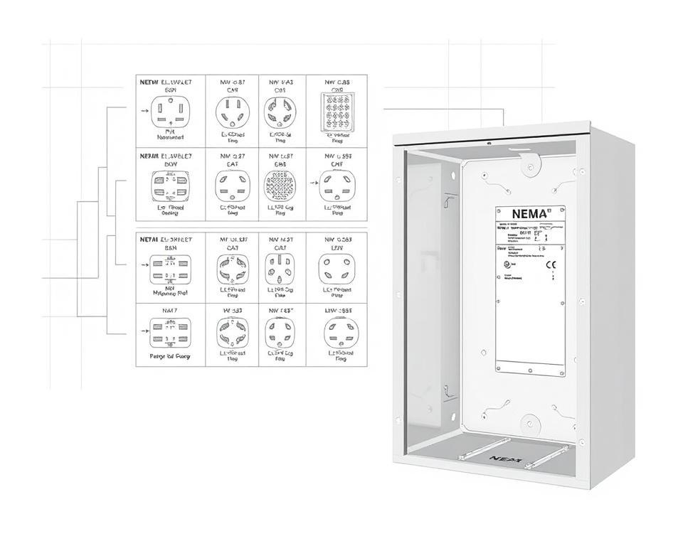
NEMA Outlet Wiring Explained
NEMA plug wiring varies to accommodate various energy requirements, with rotary-lock types delivering consistent interfaces in vibrating conditions. For example, the L5-15 plug is rated for 15 amperes, common in business sites, whereas the L14-20 is intended for 20 A at 125/250 V.
The NEMA labeling convention helps in picking the right plugs, highlighting attributes like polarity and connection to ground. This precision ensures that appliances function safely.
NEMA Outlet Wiring Standards
Proper wiring of NEMA sockets meets electrical standards and safety guidelines. For example, L530R receptacles should be wired for 30 A at 125 V, with L630R options for 250 voltage. Proper grounding is crucial to prevent electrical errors.
Opting for approved NEMA plugs and sockets secures safe, standard-compliant configurations. It’s critical to check authoritative standards when installing.
NEMA Motor Wiring and Applications
NEMA motor wiring is essential in electrical design, particularly for industrial use. Understanding how NEMA motor arrangement works guarantees that motors are installed for peak efficiency. Motors, like one-phase and tri-phase types, demand proper wiring to operate securely and effectively.
Summary of NEMA Motor Wiring
Comprehending NEMA motor wiring necessitates familiarity of linkages and setups. The majority of three-phase motors now support dual-voltage, meaning they can run on both low (208-230V) and high voltage (460V). Wiring at high voltage allows motors to draw less current than at low voltage. High voltage perks encompass thinner cables for the input, a significant benefit for units above 10 HP.
While both NEMA and IEC devices are used in the market, NEMA versions are typically bigger and more expensive than IEC ones for under 100 HP deployments. NEMA trips range from size 00 to 9, fit for diverse functions. A common characteristic in NEMA controllers is a Trip Class of 20, intended to trigger when a motor’s amperage goes beyond 6-fold the rated current in 10 s.
Choosing the Correct NEMA Motor Arrangement
Choosing the appropriate NEMA motor arrangement impacts overall efficiency and protection. A standard three-wire control circuit employs three wires for a start/stop pushbutton station, enabling straightforward motor control. Common three-phase configurations comprise the 12 Lead Dual Voltage and 6 Lead, facilitating Wye and Delta arrangements.
IEC motor starters commonly feature phase monitoring, boosting safety. They also feature configurable Trip Ratings for customized protection in low voltage operations. Additionally, many variants have heat protection, essential for single-phase and Dual Voltage setups.
| Configuration Type | Power Type | Amperage | Typical Use |
|---|---|---|---|
| 12 Lead Dual Voltage | Dual Voltage (208-230V / 460V) | Dependent on motor size | Applications with Wye Start and Delta Run |
| 6 Lead | Single/Dual Voltage | Up to 32 amps | Both Wye and Delta arrangements |
| Single Phase | Single Voltage | Dependent on adjustment (1-5A) | Applications with Two Speed, Two Winding |
| Delta Connection | Elevated Voltage | Depending on setup | Used for Current Transformers and various setups |
In Summary
Understanding NEMA wiring drawings and standards is vital for electrical specialists aiming to boost their expertise and follow electrical safety norms. These standards secure secure and efficient electrical setups but also avert risks linked to improper wiring. In summary, adhering to NEMA norms leads to the enhanced performance of various NEMA units and systems.
For electricians, the availability of high-quality supplies can greatly affect the result of their work. Installation Parts Supply provides a wide array of wiring supplies meeting NEMA standards. This empowers experts to access critical components for complying with these key standards. Superior resources and deep understanding of NEMA wiring schematics greatly enhance installation protection and performance.
Throughout electrical deployments, always put protection and precision first. Becoming well-versed in NEMA criteria delivers the insight needed for implementing industry standards correctly. This guarantees that every electrical connection established conforms to premium norms.
FAQ
What are NEMA wiring diagrams?
NEMA wiring drawings display the setups and connections of NEMA-standard electrical appliances. They comply with safety and performance norms defined by the National Electrical Manufacturers Association.
What makes NEMA criteria important for electrical security?
NEMA criteria are essential to establishing safety and operational standards for electrical devices. These guidelines enable electrical experts lower shock risks, device malfunctions, and fire risk.
Identify the key parts are vital in a NEMA wiring drawing?
Fundamental parts in a NEMA wiring schematic consist of circuit configurations and junction blueprints. These schematics also feature thorough markings and depict the electrical system’s different parts accurately for setups.
Identify the varieties of NEMA wiring drawings are used?
Various NEMA wiring drawings cater to various needs, including circuitry for power distribution and component interconnection schematics. Every diagram plays a specific role in electrical setups.
Which are the typical symbols found in NEMA wiring drawings?
Common symbols in these drawings depict switches, circuit breakers, receptacles, and more. Use of these symbols encourages unambiguous conveyance and accurate analysis of wiring drawings.
What are the key characteristics of correct electrical wiring drawings?
Accuracy in electrical wiring drawings is marked by their lucidity, completeness, and explicit annotation. They must align with NEMA norms to avoid mistakes in deployment.
Define a NEMA connector layout?
A NEMA connector configuration depicts electrical linkages at a connector, indicating particular pin functions. This secures reliable and optimal connections in electrical networks.
Which are the various kinds of NEMA appliances?
NEMA devices include various electrical outlets and couplers, like connectors and receptacles. They are crafted for various amperage and power requirements to meet particular application requirements.
Describe how NEMA plug wiring configured?
NEMA plug wiring hinges on particular amperage and power needs, adhering to safety standards and code compliance for diverse electrical setups.
What guidelines are there for NEMA outlet wiring?
Guidelines for connecting NEMA sockets emphasize following electrical regulations, ensuring accurate electrical polarity, and choosing correct cable sizes. This maintains both safety and functionality in electrical configurations.
What is the method to wire a NEMA motor effectively?
To connect a NEMA motor, one must grasp its particular one-phase or tri-phase arrangement. Choosing the appropriate wiring method is essential, in addition to practicing electrical protection for maximum motor efficiency.
What should I consider when choosing a NEMA motor configuration?
Selecting a NEMA motor arrangement requires an evaluation of the system’s energy requirements and operational characteristics. It’s also crucial to ensure suitability with current systems for reliable efficiency and security.